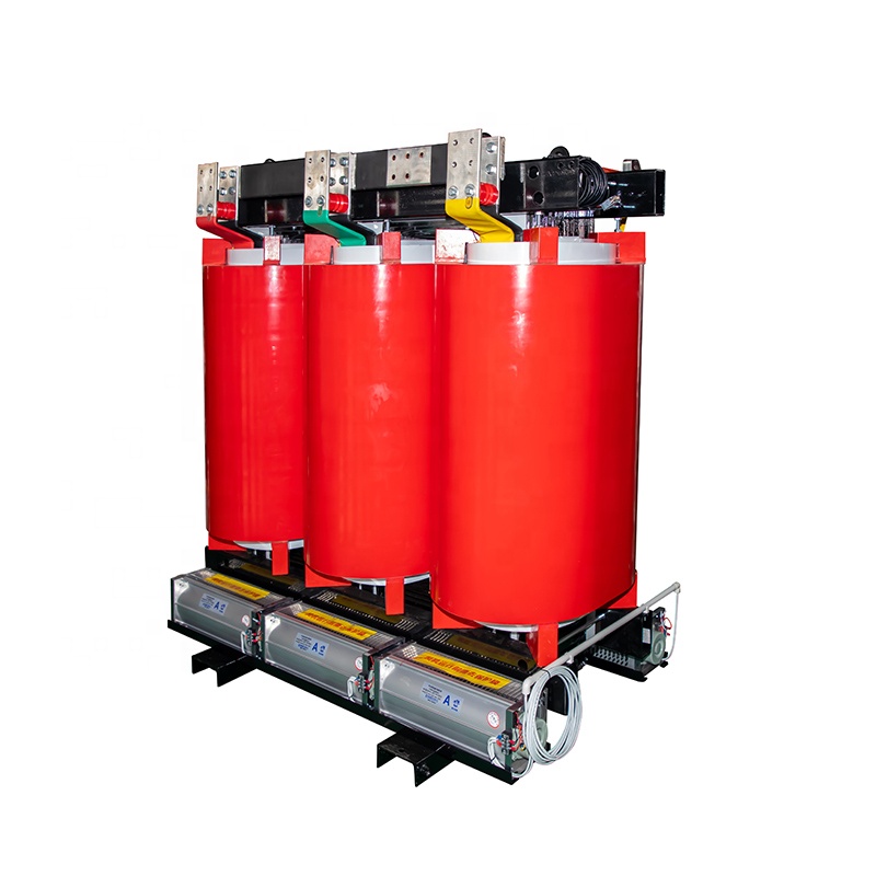
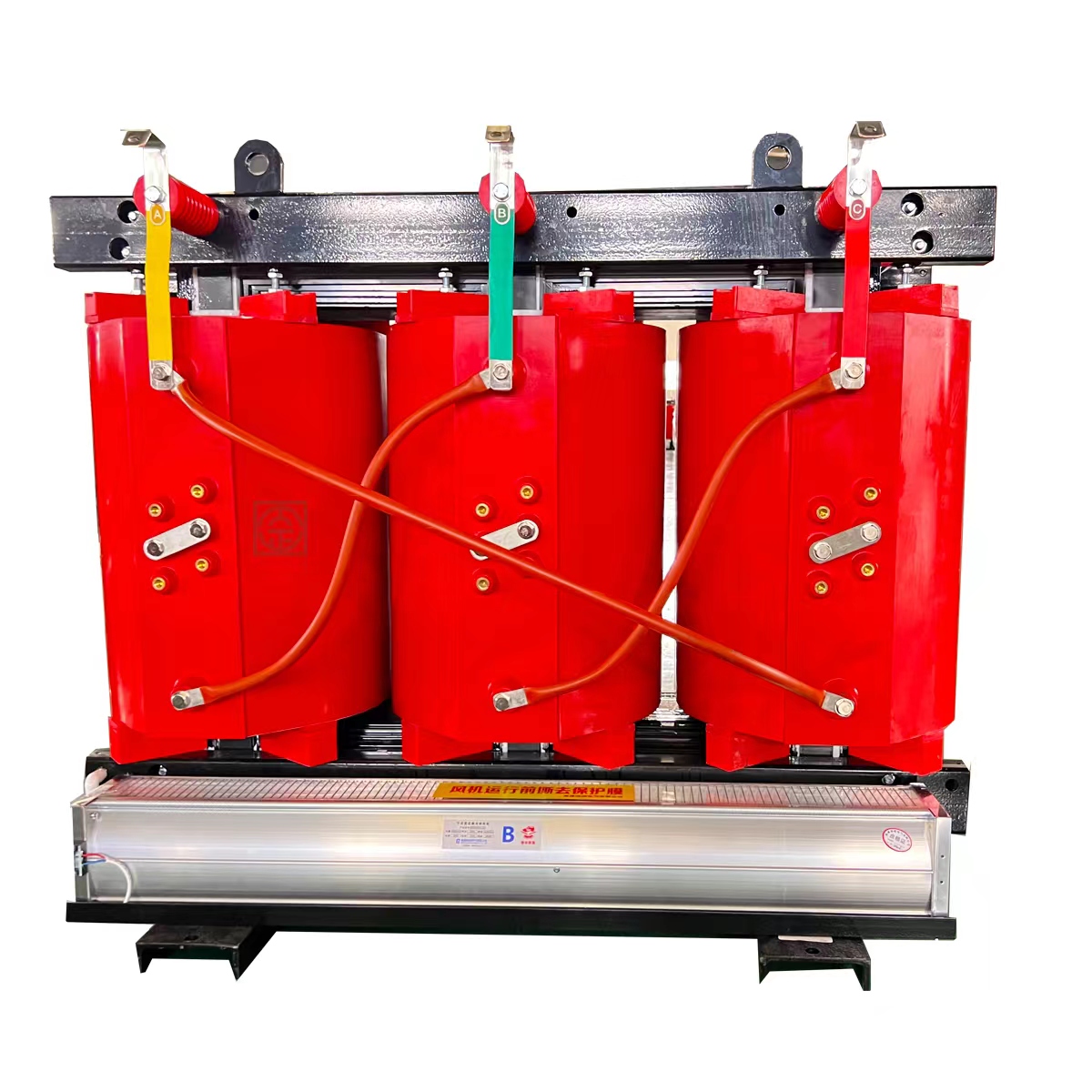
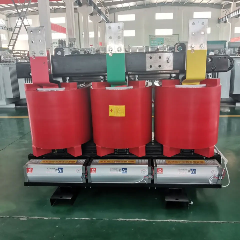
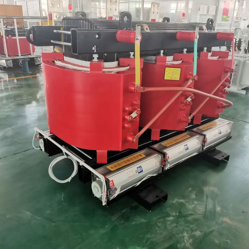
10kv three phase dry transformer
Featured:
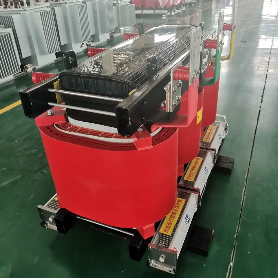
The high voltage winding is made of enameled copper wire or double glass fiber wrapped flat copper wire, and the low voltage winding is made of copper foil. The high-voltage winding is filled with glass fiber mat, and imported epoxy resin without filler is cast in a vacuum state. After curing, it forms a solid whole with good mechanical strength, small partial discharge and high reliability.Quote Now
Description
| Model Number | SCB11/SCB 12/SCB13 |
| Phase | Three |
| Coil Number | 2 |
| Usage | POWER DISTRIBUTION |
| Coil Structure | ROUND |
| Input Voltage | 400v/3kv/6kv/10kv/35kv |
| Standard | IEC ANSI IEEE |
| Warranty | 5 Years |
Characteristics of dry-type transformers
- The high voltage winding is made of enameled copper wire or double glass fiber wrapped flat copper wire, and the low voltage winding is made of copper foil. The high-voltage winding is filled with glass fiber mat, and imported epoxy resin without filler is cast in a vacuum state. After curing, it forms a solid whole with good mechanical strength, small partial discharge and high reliability.
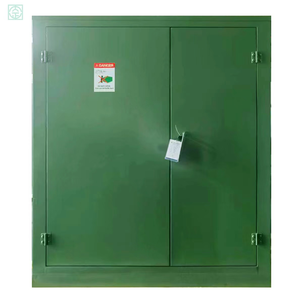
- It is flame retardant, explosion-proof, does not pollute the environment, and can be installed in load centers.
- The coil does not absorb moisture, and the core and clamps have been treated with special processes to operate in 100% relative humidity and other harsh environments. Intermittent operation does not require dehumidification treatment.
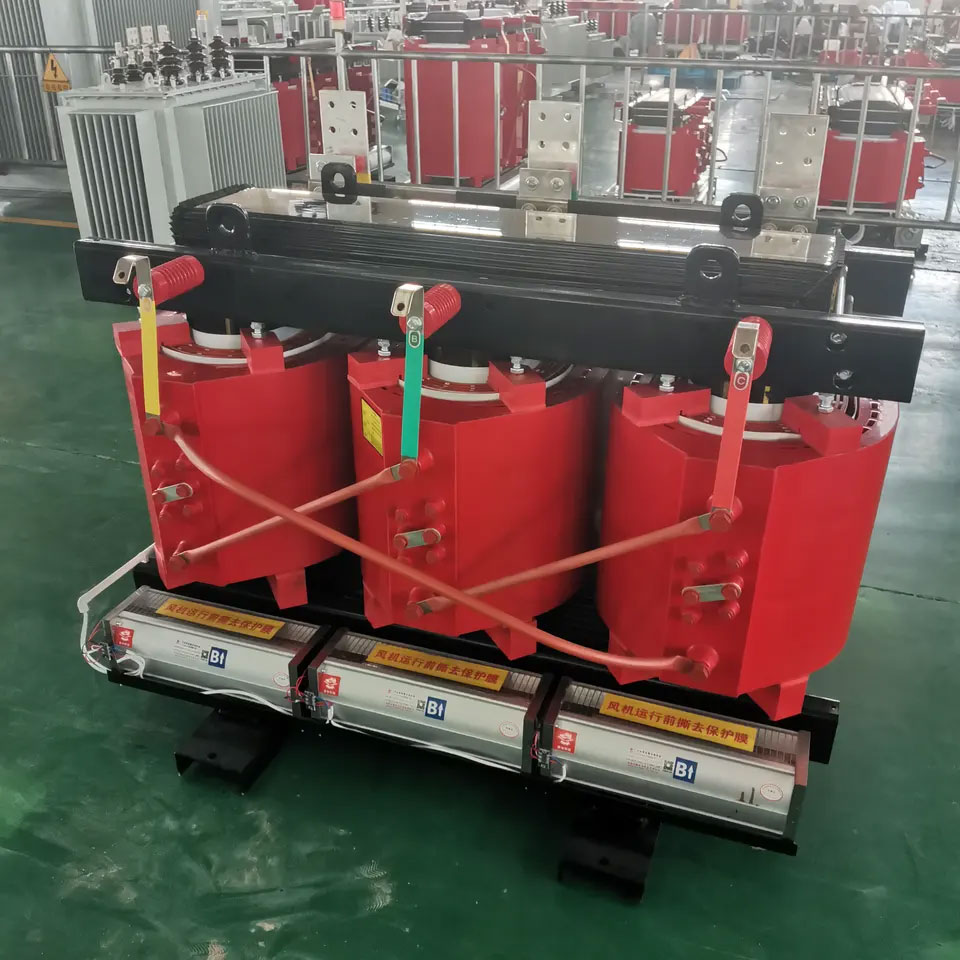
- High resistance to short circuit and lightning impact.
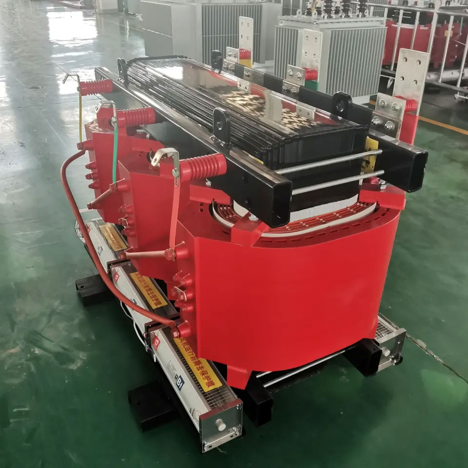
- The resin insulation layer inside and outside the coil is thin and has good heat dissipation performance. The cooling method generally adopts air natural cooling (AN). An air cooling system (AF) can be configured for transformers of any protection level.
- Low loss, good power saving effect, economical operation and maintenance-free.
- Small size, light weight, small footprint and easy installation.
TECHNICAL PARAMETER
| Rated current(A) | Voltage combination and tap range | link group | No-load current(%) | Load loss(W) | load loss(W) | short circuit impedance(%) | ||||||
| HV
(KV) |
High voltage tap range % | LV
(KV) |
NX1 | NX2 | NX3 | NX1 | NX2 | NX3 | ||||
| 30 | 6
6.3 6.6 10 10.5 11 |
±2×2.5
±5 |
0.4 | Dyn11
Yyn0 |
2 | 105 | 130 | 150 | 640 | 640 | 710 | 4.0 |
| 50 | 2 | 155 | 185 | 215 | 900 | 900 | 1000 | |||||
| 80 | 1.5 | 210 | 250 | 295 | 1240 | 1240 | 1380 | |||||
| 100 | 1.5 | 230 | 270 | 320 | 1415 | 1415 | 1570 | |||||
| 125 | 1.3 | 270 | 320 | 375 | 1665 | 1665 | 1850 | |||||
| 160 | 1.3 | 310 | 365 | 430 | 1915 | 1915 | 2130 | |||||
| 200 | 1.1 | 360 | 420 | 495 | 2275 | 2275 | 2530 | |||||
| 250 | 1.1 | 415 | 490 | 575 | 2485 | 2485 | 2760 | |||||
| 315 | 1 | 510 | 600 | 705 | 3125 | 3125 | 3470 | |||||
| 400 | 1 | 570 | 665 | 785 | 3590 | 3590 | 3990 | |||||
| 500 | 1 | 670 | 790 | 930 | 4390 | 4390 | 4880 | |||||
| 630 | 0.85 | 775 | 910 | 1070 | 5290 | 5290 | 5880 | |||||
| 630 | 0.85 | 750 | 885 | 1040 | 5365 | 5365 | 5960 | 6.0 | ||||
| 800 | 0.85 | 875 | 1035 | 1215 | 6265 | 6265 | 6960 | |||||
| 1000 | 0.85 | 1020 | 1205 | 1415 | 7315 | 7315 | 8130 | |||||
| 1250 | 0.85 | 1205 | 1420 | 1670 | 8720 | 8720 | 9690 | |||||
| 1600 | 0.85 | 1415 | 1665 | 1960 | 10555 | 10555 | 11730 | |||||
| 2000 | 0.75 | 1760 | 2075 | 2440 | 13005 | 13005 | 14450 | |||||
| 2500 | 0.75 | 2080 | 2450 | 2880 | 15445 | 15445 | 17170 | |||||